Inspecting 3D printed parts with a digital microscope removes the guesswork from troubleshooting printing errors. This guide explains how to properly set up your equipment, examine models for hidden flaws, identify common manufacturing defects, and adjust your settings for flawless, high-quality prints.
Prepare the Printed Part
Accurate inspection starts with a clean, stable sample. Dirt, uncured resin, and loose plastic can resemble defects under magnification.
Clean the Surface
For resin prints, wash the part in isopropyl alcohol and complete the recommended UV curing process. Uncured resin is highly reflective and may hide the true surface texture. For filament prints, remove strands, support debris, and plastic dust with a soft brush. Avoid sanding or polishing before inspection because this can remove evidence of the original defect.
Mark the Area to Inspect
At high magnification, sections of single-color plastic can look identical. If you already see a suspicious area, place a small removable mark beside it with a fine marker or low-tack tape. Do not cover the defect itself.
Secure the Part in Place
Use mounting putty, a small clamp, a vise with soft jaws, or a weighted holder to keep the object still. Hand-holding the part causes movement and makes focusing difficult. Make sure the holder does not bend thin features or block the inspection area.
Set Up the Digital Microscope
A stable microscope, suitable working distance, and angled lighting are more important than maximum magnification.
Start With Low Magnification
Always begin your examination using the lowest optical power available. Zooming in too closely right away makes it incredibly difficult to understand which part of the printed geometry you are actually viewing. A wide field of view allows you to see several layer lines at once and evaluate the overall consistency of the extrusion. Once you have the object centered and focused, you can gradually increase the magnification to scrutinize specific microscopic details.
Adjust the Working Distance
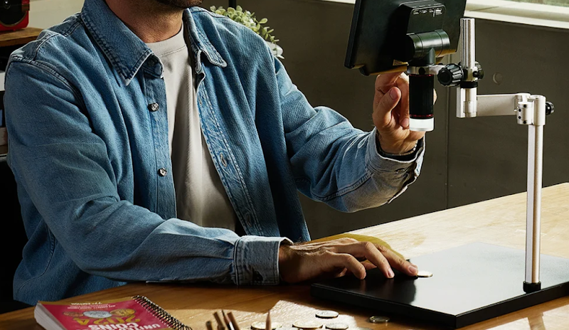
Working distance is the physical space between the camera lens and the top surface of your plastic model. You need enough clearance to comfortably move the piece around without accidentally bumping it into the expensive camera housing. Raise the main optical unit high enough on its stand to give yourself plenty of maneuvering room, then use the internal focus wheel to bring the horizontal layers into sharp view.
Position the Lighting
Proper illumination is the absolute secret to inspecting 3D printed objects. Direct overhead lighting will wash out the plastic and hide the texture of your layer lines entirely. Instead, you need angled illumination to cast shadows across the microscopic ridges. A device like Tomlov DM9 7″ LCD Digital Microscope is fantastic for this because it features adjustable side lights. Aiming these side lights at a shallow angle makes every single layer line and surface imperfection pop instantly.
Focus on the Surface
Getting a crisp image requires slow and deliberate adjustments. Turn the main focus dial gently until the tiny ridges of plastic become clearly defined on your monitor. Because printed parts are three-dimensional, the top of a curve might be in focus while the bottom is blurry. Focus specifically on the layer you want to evaluate and do not worry if the background falls out of focus during the inspection.
Inspect the Part Step by Step
A consistent inspection sequence reduces the chance of overlooking important defects.
Scan the Entire Surface
Begin your inspection by slowly panning the camera across the large flat walls of your print. You are looking for overall consistency in the plastic lines. The layers should look like perfectly stacked cylinders of equal thickness. Watch for any sudden wavy patterns, thick bands, or repeating shifts that indicate a loose mechanical belt or a bent threaded rod on your 3D printer.
Check Corners and Thin Features
Sharp corners and very thin towers are typically where a printer struggles the most. Move your focus to these delicate areas. You want to see crisp angles without excessive bulging or rounded corners. If the plastic looks like it is pooling heavily at the edges, your machine is likely slowing down too much at the corner and depositing excess material.
Inspect Holes and Joined Sections
Examine the perimeters where the solid infill meets the outer walls, as well as the interior edges of screw holes. There should be a slight, consistent overlap where these two sections bond together. If you see deep empty gaps between the infill and the outer wall, your parts will lack structural integrity and break easily under physical stress.
View Defects From Different Angles
A single viewing angle rarely tells the whole story. If you spot a strange blob or a gap, unclamp your model and rotate it to view the exact same defect from the side. Viewing an anomaly from multiple perspectives helps you determine if the issue is a deep structural void extending into the core or just a superficial blemish resting lightly on the outer skin.
Identify Common Printing Defects
Interpret the microscope image together with the defect’s position, pattern, and frequency.
Under Extrusion and Missing Material
When your printer fails to push enough plastic through the nozzle, the result is under extrusion. On a digital screen, this looks like thin, frail, or broken lines of plastic with empty black space visible between them. The layers will appear starved and separated rather than tightly squished together. This visual evidence clearly points to a partial nozzle clog or an incorrect extrusion multiplier setting.
Layer Separation and Small Cracks
Also known as delamination, this occurs when one layer of plastic cools too quickly and fails to bond with the layer below it. Under magnification, you will clearly see a horizontal split dividing two stacked lines. Identifying these micro cracks early prevents the entire component from splitting apart when you attempt to install a screw or apply heavy mechanical load.
Stringing and Surface Blobs
Stringing happens when plastic oozes from the nozzle while the print head travels across an empty space. Microscopically, these look like tiny spider webs or thick hairy branches clinging to the sides of your model. Surface blobs look like irregular warts of plastic deposited randomly on an otherwise smooth wall, usually indicating an issue with your retraction settings.
Resin Voids and Support Damage
If you use a liquid resin printer, your defects will look slightly different. Look for perfectly round crater holes on the surface, which indicate trapped air bubbles. You should also closely examine the tiny divots left behind where you snapped off the support structures. High magnification will reveal if those support points dug deeply into the model and compromised the smooth exterior finish.
Use the Results to Improve Print Quality
An inspection is only valuable if you use the information to improve the model. Your microscopic findings will dictate exactly what you need to do next in your slicing software.
Adjust Temperature and Flow
Once you visually confirm a specific defect, you can confidently alter your software settings. If your microscope revealed starved layers and gaps, increase your extrusion multiplier or raise your nozzle temperature by five degrees to help the plastic flow better. If you saw heavy pooling and bloated corners, lower the flow rate slightly to prevent the machine from over extruding material.
Improve Cooling and Layer Adhesion
Finding micro cracks and layer separation means your material is cooling inconsistently. If you are printing with standard filament, you might need to decrease your cooling fan speed to allow the plastic to bond securely. Conversely, if you observed drooping overhangs and messy bridges, increasing the fan speed will freeze the plastic into place faster before gravity pulls it down.
Change Support Placement
If your digital inspection showed severe scarring from support removal, you need to revisit your slicing software. Adjust the support density or change the contact point size to make the temporary structures easier to break away. Viewing the damage closely helps you understand exactly how much material is being torn out of your final product during the cleanup phase.
Reprint and Inspect Again
After making one adjustment, print the same test part with the same material. Photograph the original and revised parts under similar magnification and lighting. A direct comparison shows whether gaps, cracks, blobs, or support damage have improved. Record the printer settings so successful changes can be repeated.
Conclusions
Perfecting the 3D printing process requires more than just guessing which software settings to change. By incorporating an HDMI digital microscope into your workspace, you gain the ability to accurately diagnose microscopic extrusion issues, layer adhesion failures, and hidden structural gaps. Taking the time to properly prepare your parts, optimize your lighting angles, and methodically scan for specific anomalies empowers you to make highly informed adjustments. As you continue to inspect your work and adjust your machine, you will confidently produce stronger, cleaner, and incredibly precise printed parts every single time.